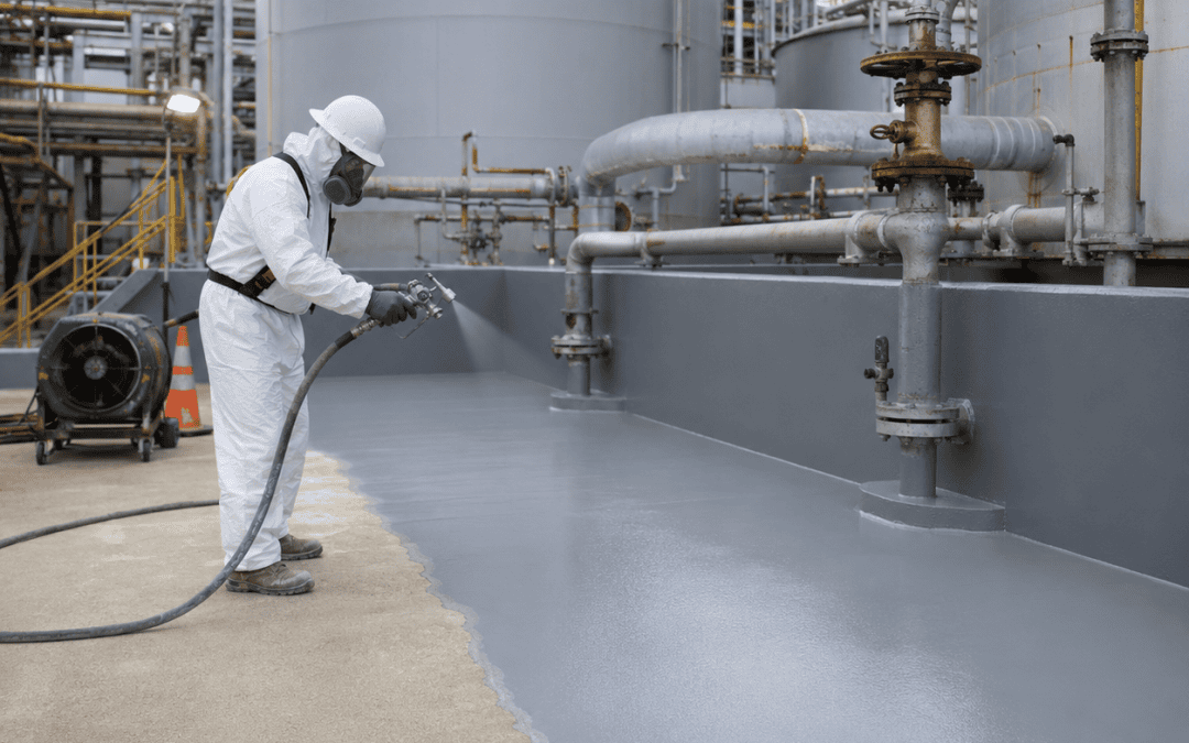
Containment systems for oil and gas facilities help control leaks, spills, and chemical exposure by creating durable barriers around tanks, transfer areas, processing equipment, and other high-risk operating zones.
Quick Answer
Oil and gas containment systems are designed to keep petroleum products, chemicals, wastewater, and process fluids from spreading beyond their intended storage or handling areas.
A complete containment strategy may include primary tank linings, secondary containment walls, berms, coated concrete pads, trench systems, sealed penetrations, chemical-resistant membranes, and repair systems for damaged substrates.
The appropriate system depends on the stored material, exposure conditions, traffic, temperature, facility layout, substrate condition, and required response capacity.
Why Containment Is Critical in Oil and Gas Operations
Oil and gas facilities handle materials that can create significant operational, environmental, and financial consequences when a leak or spill occurs.
Storage tanks, loading areas, pump stations, processing equipment, transfer lines, chemical treatment systems, and wastewater zones may all require a planned containment approach.
The purpose of containment is not limited to regulatory compliance. A properly designed system also helps protect:
- Employees and contractors
- Soil and groundwater
- Nearby drainage systems
- Process equipment
- Facility structures
- Production continuity
- Emergency-response teams
- Long-term asset value
Containment failure can expand a localized equipment problem into a much larger cleanup and shutdown event. For that reason, facility managers should evaluate both the material used in the containment system and the condition of the underlying structure.
Primary Containment vs. Secondary Containment
Primary containment is the first barrier that directly holds the stored or processed material.
Examples include:
- Storage tanks
- Process vessels
- Piping
- Sumps
- Lined pits
- Tank interiors
- Chemical-processing equipment
Secondary containment is the backup system intended to capture material if the primary system leaks or fails.
Examples include:
- Concrete containment areas
- Dikes and berms
- Curbed pads
- Lined trenches
- Coated tank farms
- Spill-control basins
- Containment walls
- Membrane-lined areas
A reliable oil and gas secondary containment system should form a continuous barrier. Cracks, joints, penetrations, drains, seams, and wall-to-floor transitions must be addressed because these areas often become the first paths of escape.
Common Oil and Gas Containment Applications
Containment requirements vary across facilities, but several applications are common.
Tank Farms
Tank farms may require containment around multiple storage tanks, piping connections, valves, and transfer points.
The system must account for:
- Exposure to petroleum products
- Outdoor weather
- Standing water
- Vehicle or equipment traffic
- Thermal expansion
- Cracks and joints
- Drainage control
- Existing coating deterioration
The containment area should be inspected as a complete assembly rather than as separate walls and floors.
Loading and Unloading Areas
Truck and rail transfer areas are vulnerable to hose failures, overfills, valve leaks, and connection errors.
These areas may require coated concrete, curbs, trench drains, sump systems, and chemical-resistant lining materials. The system must also withstand traffic, abrasion, impact, and frequent cleaning.
Processing and Chemical-Feed Areas
Oil and gas operations may use acids, caustics, treatment chemicals, solvents, and other materials that require stronger chemical resistance than standard concrete sealers or general-purpose coatings can provide.
The selected containment lining should be evaluated against the actual chemical concentration, temperature, duration of exposure, and cleaning procedures.
Produced-Water and Wastewater Areas
Produced water and process wastewater may contain hydrocarbons, salts, treatment chemicals, and suspended solids.
Containment systems in these environments may need to resist chemical attack, moisture, abrasion, and repeated wet-dry cycles.
Pump Stations and Equipment Pads
Leaks around pumps, compressors, valves, and mechanical equipment may appear minor but can spread across unprotected concrete or enter drains.
A sealed and properly detailed containment surface can make leaks easier to identify, isolate, and clean.
What Causes Containment Systems to Fail?
Containment systems often fail gradually.
Common causes include:
- Improper surface preparation
- Coating incompatibility
- Cracks in concrete
- Corrosion beneath the lining
- Failed joints or seams
- Moisture vapor transmission
- UV exposure
- Thermal cycling
- Abrasion
- Vehicle traffic
- Chemical attack
- Impact damage
- Poor detailing around penetrations
- Inadequate lining thickness
- Installation over contaminated surfaces
A new coating should not be installed until the failure mechanism has been identified. Otherwise, the replacement system may develop the same problem.
Step 1: Inspect the Existing Containment Area
A professional containment project begins with an inspection of the substrate, coating system, joints, drains, penetrations, walls, curbs, and transitions.
The inspection should identify:
- Cracks
- Spalling
- Delamination
- Blisters
- Soft or deteriorated concrete
- Corrosion
- Standing water
- Failed sealants
- Exposed aggregate
- Damaged membranes
- Previous patching
- Areas of repeated chemical exposure
The facility should also document the materials handled in the area and any known spill history.
Step 2: Define the Chemical and Operating Exposure
Material selection must be based on actual service conditions.
Important questions include:
- What product must the system contain?
- What is the chemical concentration?
- What temperature range is expected?
- Is exposure continuous or occasional?
- How long might a spill remain before cleanup?
- Will vehicles or heavy equipment cross the area?
- Is the system indoors or outdoors?
- Will the area be pressure-washed or steam-cleaned?
- Is movement expected at joints or transitions?
- How quickly must the area return to service?
These factors help determine whether the system requires epoxy, polyurea, polyurethane, vinyl ester, fiberglass reinforcement, elastomeric materials, or another engineered lining approach.
Step 3: Repair the Substrate
The containment lining cannot perform reliably over an unstable or damaged substrate.
Repairs may include:
- Filling cracks and voids
- Rebuilding deteriorated concrete
- Repairing wall-to-floor transitions
- Replacing damaged joint material
- Patching holes
- Repairing corroded steel
- Rebuilding curbs
- Correcting low areas
- Sealing penetrations
- Reinforcing high-stress locations
Structural repairs and coating repairs should be treated as related but separate parts of the project.
Step 4: Prepare the Surface
Surface preparation is one of the most important parts of containment installation.
The contractor may use abrasive blasting, shot blasting, grinding, scarification, pressure cleaning, or other methods depending on the substrate and system.
Preparation removes:
- Failed coatings
- Oils
- Dirt
- Chemical residue
- Weak concrete
- Rust
- Scale
- Surface contamination
It also creates the profile required for the new lining to bond.
Concrete moisture and environmental conditions should be evaluated before application. Installing a lining over excessive moisture can contribute to blistering or loss of adhesion.
Step 5: Detail Joints, Penetrations, and Transitions
Containment systems commonly fail at their weakest points.
These include:
- Expansion joints
- Control joints
- Pipe penetrations
- Drains
- Sumps